
Applications
Where this spring style fits
Review best-fit uses, assembly constraints and situations where another spring style may be a better choice.
View application guidance →Wire Forms
Custom 2D and 3D wire parts formed to a drawing when the component needs to locate, retain, connect, guide or support another part rather than behave like a conventional coil spring.
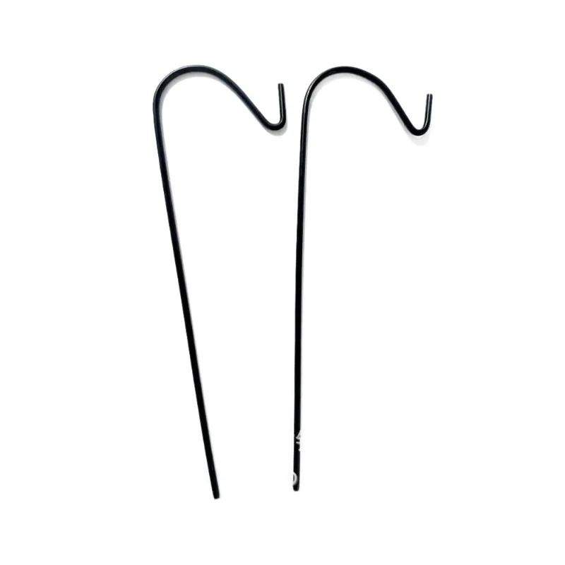
Wire-formed components cover shapes that cannot be described well by spring diameter and free length alone. The functional geometry may include bends in several planes, loops, hooks, offsets and straight sections. The drawing therefore becomes the primary manufacturing specification.
CNC wire forming can produce repeatable multi-bend shapes, but inspection planning matters as much as the forming path. For complex parts, a dedicated checking fixture may be more reliable than measuring every segment independently.
Product Data
Use these data points to compare practical starting dimensions and material options. Final production specifications are confirmed against your drawing and working conditions.
| Model | Wire dia. | OD | ID | Free length | Rate | Material | Coils | Max load |
|---|---|---|---|---|---|---|---|---|
| SW-400-0310-0718-0773 | 4 mm | 30.96 mm | 22.96 mm | 71.83 mm | 32.194 | 304 Stainless Steel | 3.5 | 459.73 |
| SW-200-0379-0886-0792 | 2 mm | 37.92 mm | 33.92 mm | 88.65 mm | 0.533 | Inconel X-750 | 6.4 | 8.49 |
| SW-200-0404-0680-0750 | 2 mm | 40.45 mm | 36.45 mm | 68.05 mm | 0.342 | 301 Stainless Steel | 7.1 | 3.66 |
| SW-400-0297-1661-0742 | 4 mm | 29.7 mm | 21.7 mm | 166.06 mm | 19.253 | Beryllium Copper (QBe2) | 4.7 | 746.43 |
| SW-050-0062-1535-0726 | 0.5 mm | 6.18 mm | 5.18 mm | 153.46 mm | 0.503 | 60Si2MnA Spring Steel | 6.7 | 21.48 |
| SW-400-0523-0651-0729 | 4 mm | 52.27 mm | 44.27 mm | 65.12 mm | 4.014 | 60Si2MnA Spring Steel | 5.6 | 52.14 |
| SW-150-0146-1901-0769 | 1.5 mm | 14.63 mm | 11.63 mm | 190.06 mm | 5.511 | 301 Stainless Steel | 3.5 | 290.01 |
| SW-300-0322-1131-0782 | 3 mm | 32.24 mm | 26.24 mm | 113.06 mm | 4.05 | 304 Stainless Steel | 6.9 | 85.7 |
| SW-030-0062-1182-0758 | 0.3 mm | 6.21 mm | 5.61 mm | 118.23 mm | 0.035 | 316 Stainless Steel | 9.6 | 0.81 |
| SW-400-0306-0368-0786 | 4 mm | 30.63 mm | 22.63 mm | 36.84 mm | 36.537 | 316 Stainless Steel | 3.2 | 368.3 |
| SW-300-0569-1508-0774 | 3 mm | 56.94 mm | 50.94 mm | 150.81 mm | 0.445 | 304 Stainless Steel | 10 | 9.25 |
| SW-200-0287-1945-0767 | 2 mm | 28.72 mm | 24.72 mm | 194.54 mm | 2.071 | Oil-Tempered Spring Wire (SWO) | 4 | 107.19 |
| SW-200-0241-0832-0738 | 2 mm | 24.13 mm | 20.13 mm | 83.23 mm | 1.286 | 301 Stainless Steel | 9.9 | 24.86 |
| SW-100-0181-1764-0739 | 1 mm | 18.09 mm | 16.09 mm | 176.41 mm | 0.213 | 60Si2MnA Spring Steel | 9.3 | 4.61 |
| SW-150-0204-0652-0746 | 1.5 mm | 20.4 mm | 17.4 mm | 65.23 mm | 1.797 | 301 Stainless Steel | 3.6 | 23.8 |
| SW-400-0689-1778-0764 | 4 mm | 68.92 mm | 60.92 mm | 177.82 mm | 1.717 | 301 Stainless Steel | 4.7 | 80.61 |
Rate: N/mm; maximum load: N. Dimensions are in millimeters.
Engineering Data
Use these data points to compare geometry, material and working parameters when defining your custom spring. Final values are reviewed and confirmed for the actual assembly before production.
| Configuration | Data type | Key parameters | Material / basis |
|---|---|---|---|
| Engineering Data 01 | Engineering Data |
|
Spring steel / stainless / alloy |
| Engineering Data 02 | Manufacturing Range |
|
Multiple wire materials |
| Engineering Data 03 | Design Input |
|
Per drawing |
| Engineering Data 04 | Manufacturing Range |
|
Multiple spring-wire materials |
Design note: dimensions, force / torque, material, tolerances, fatigue life and compliance are finalized against your drawing and operating conditions during quotation.
Next Design Decisions
Once the spring style is selected, confirm how it works in the assembly, which material suits the environment, how it will be manufactured and which dimensions and performance points should be controlled on the drawing.
Applications
Review best-fit uses, assembly constraints and situations where another spring style may be a better choice.
View application guidance →Materials
Carbon steel, stainless steel and spring wire are common starting points. The right choice depends on whether the part needs elastic deflection, corrosion resistance, welding, conductivity or mainly geometric stiffness.
Compare spring materials →Manufacturing
Review forming, heat treatment, secondary operations, inspection and the path from first samples to repeat production.
View manufacturing capabilities →Engineering Data
Matching material and wire-diameter pages provide additional design data for material and size selection.
Open Spring Engineering Guide →Material Direction
The links below are selection guides, not a claim that every grade is suitable for every size or load.
Engineering Support
Use these guides to compare material, wire diameter and standard requirements before finalizing the product drawing.
Compare Designs
Use these alternatives when the available space, connection style, travel or force direction changes.
Wire Forms
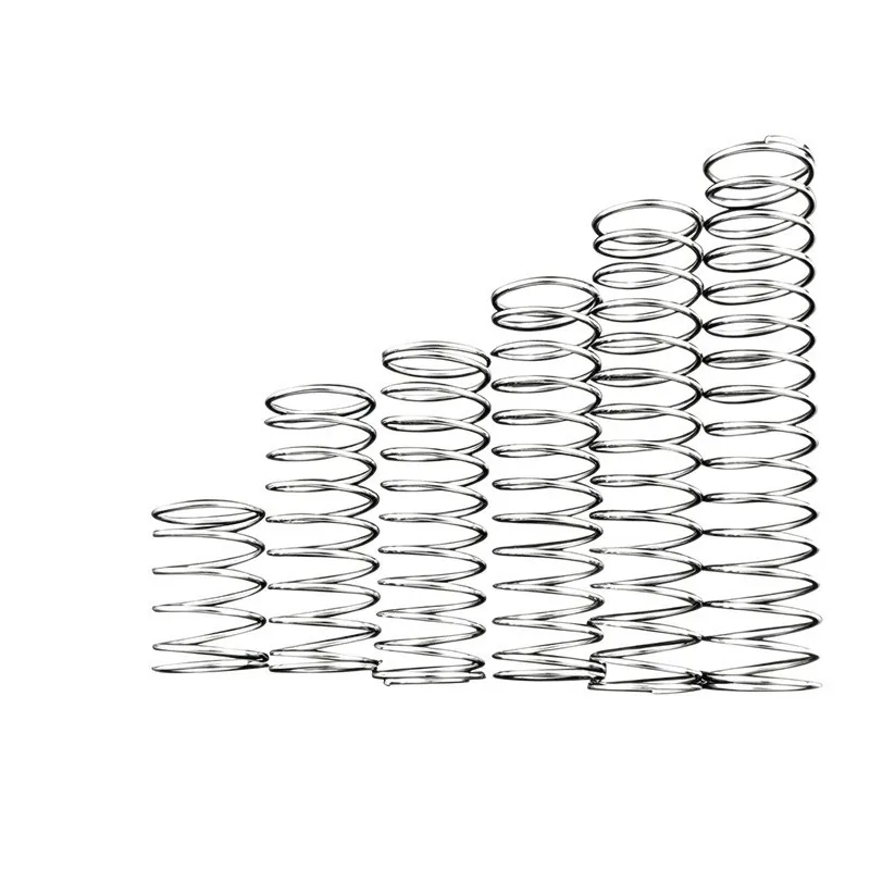
A made-to-drawing spring form for mechanisms that need elastic behavior but cannot be served by a standard compression, extension or torsion geometry.
Wire Forms
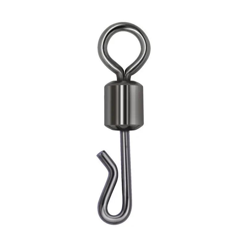
Made-to-drawing wire clips, hooks and rings used to retain, hang, connect or locate parts where a standard spring geometry is not required.

Wire Forms
Custom formed-wire brackets, handles and frames for lightweight support, carrying, guiding and structural functions made directly to the product geometry.
Product Questions
No. Some are mostly structural retainers or connectors, while others use controlled elastic deflection in one or more sections. The intended function should be stated on the RFQ.
It helps with geometry, but a 2D drawing is still useful for material, wire size, tolerances, finish and critical dimensions.
RFQ
A drawing is ideal. If you do not have one yet, provide the dimensions, load or torque, travel, environment and expected quantity that matter in the assembly.
CustomSprings Engineering Catalog
Send your dimensions, quantity and drawing for engineering review.