
Key Takeaways
- Spring pitch is the axial distance between coil centers and directly controls travel and solid height in compression springs.
- Free length can be calculated from pitch using: free length = (active coils + 1) × pitch + 2 × wire diameter for squared and ground ends.
- Maximum deflection before coil bind equals free length minus solid height; always leave a safety margin.
- Complete design inputs include wire diameter, coil count, free length, load, travel, cycle life, and environment.
- Use the site's Spring Guide and RFQ process to validate calculations and avoid trial-and-error redesigns.
A product engineer at a medical device company once sent a compression spring drawing with a note: “It bottoms out too early.” The spring had a free length of 1.5 inches and a solid height of 0.9 inches, leaving only 0.6 inches of travel. The design required 0.75 inches. The engineer had not calculated solid height from pitch and wire diameter. That single oversight turned a straightforward spring into a redesign cycle. Spring pitch is not a number you pick arbitrarily—it is the geometric foundation that determines travel, solid height, and load-deflection behavior. This article explains spring pitch in the context of spring design calculation, so you can specify compression springs that meet travel requirements without trial-and-error.
Answer-First Explanation of Spring Pitch
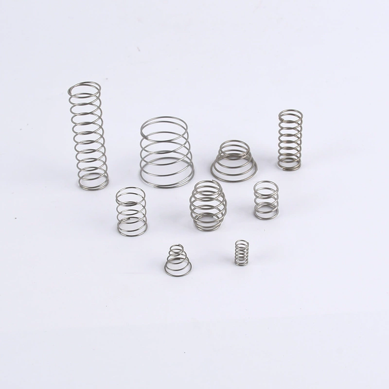
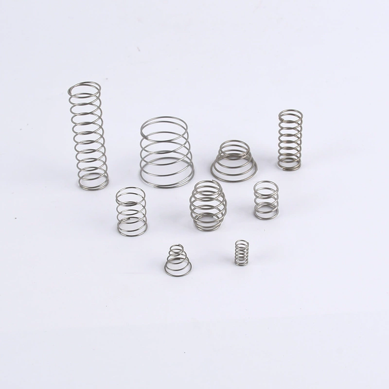
Spring pitch is the axial distance from the center of one active coil to the center of the next active coil, measured along the spring axis. In a compression spring, pitch controls how much the spring can deflect before coils touch. A larger pitch allows more travel; a smaller pitch reduces free length for a given number of coils. Pitch is distinct from coil spacing (the gap between adjacent wire surfaces) and from lead, which is the axial advance per complete revolution. For most compression springs with constant pitch, lead equals pitch. In variable-pitch springs, pitch changes along the length to create a progressive rate. Understanding pitch is essential for spring design calculation because it directly affects solid height, travel, and stress distribution.
Key Formulas and Engineering Relationships
Several relationships connect pitch to spring performance. These are standard mechanical engineering formulas; exact values require project-specific inputs.
- Solid height (for squared and ground ends): Solid height = (total number of coils) × wire diameter. For closed ends, it is (total coils + 1) × wire diameter. Pitch does not appear directly, but it determines the maximum number of active coils that fit within a given free length.
- Free length from pitch: Free length = (active coils + 1) × pitch + 2 × wire diameter (for squared and ground ends). This assumes constant pitch and includes the end coils.
- Pitch from free length: Pitch = (free length − 2 × wire diameter) / (active coils + 1). This is the inverse, useful when you know the required free length and coil count.
- Maximum deflection before coil bind: Maximum deflection = free length − solid height. This is the absolute travel limit; in practice, you should leave a gap between coils at maximum load to avoid wear and fatigue.
- Spring rate (k): k = (G × d⁴) / (8 × D³ × N), where G is shear modulus, d is wire diameter, D is mean coil diameter, and N is the number of active coils. Pitch does not directly appear in the rate formula, but it constrains N for a given free length.
These formulas are starting points. Real springs involve tolerances, end conditions, and material behavior that require engineering confirmation. For reference data and material properties, see the site’s Spring Guide.
Inputs Engineers Need Before Calculation
Before you can calculate pitch, you need a complete set of design inputs. Missing any one of these can lead to a spring that does not fit or perform as intended.
- Dimensions: Wire diameter, outside or inside diameter, free length, and number of active coils. These are the core geometry parameters.
- Material: Music wire, stainless steel, chrome silicon, or other alloys. Material affects shear modulus, allowable stress, and fatigue life. Material pages on the site provide selection guidance.
- Load and deflection: The force required at one or more deflected positions. This determines spring rate and, combined with geometry, the required pitch.
- Travel: The total deflection from free length to maximum load. Travel must be less than the available deflection before coil bind.
- Cycle life: The number of cycles expected. Fatigue life depends on stress range, which is influenced by pitch and coil diameter. High cycle counts may require lower stress and thus larger pitch or different geometry.
- Environment: Temperature, corrosion, and presence of shock or vibration. These factors influence material choice and surface treatment, which in turn affect allowable stress and pitch.
If any of these inputs are unknown, engineering confirmation is required before finalizing a design. The RFQ page can help you start that conversation.
Design Trade-offs and Warning Signs
Pitch is always a compromise. Increasing pitch allows more travel but increases free length, which may not fit the envelope. Decreasing pitch reduces free length but limits travel and can lead to coil bind. Here are common trade-offs and warning signs.
- Coil bind: If calculated maximum deflection is close to free length minus solid height, the spring will bottom out under load. Always leave a safety margin; the exact margin depends on application and should be confirmed by engineering.
- Surge and resonance: Large pitch can create uneven stress distribution and increase susceptibility to surge. Variable pitch can mitigate this but adds manufacturing complexity.
- Fatigue: High stress at the inside of coils, often exacerbated by tight pitch, reduces cycle life. If cycle life is critical, consider stress-relieved ends or different material.
- Manufacturing limits: Very small pitch relative to wire diameter can be difficult to manufacture consistently. Very large pitch may cause instability or buckling in compression springs.
- End conditions: Squared and ground ends are common for compression springs, but closed or open ends change the relationship between pitch and free length. Specify end type clearly.
If you see any of these warning signs, revisit your inputs or consult the site’s reference data for guidance on stress and travel limits.
When to Use the Spring Guide, Calculators, or Reference Data
Hand calculations are useful for initial sizing, but they are not a substitute for validated engineering data. The site’s Spring Guide provides material properties, stress correction factors, and design equations. For compression springs, the guide includes sections on pitch, solid height, and buckling. If you need to iterate quickly, a spring calculator can help, but be aware that calculators use assumptions that may not match your application. Always verify critical dimensions and loads with a prototype or engineering analysis. For custom designs, the RFQ process ensures that a spring engineer reviews your inputs and confirms feasibility.
How to Prepare Data for a Custom Spring Design or RFQ
When you request a custom spring, providing complete and accurate data speeds up the process and reduces the risk of multiple iterations. Here is a checklist of what to include.
- Application description: What the spring does, where it is used, and any space constraints.
- Dimensions: Wire diameter, outside diameter, free length, and number of coils (if known). If not known, provide the envelope and load requirements.
- Load and deflection: Required force at specific deflections, or a load-deflection curve.
- Travel: Maximum deflection from free length.
- Cycle life: Expected number of cycles and whether fatigue is a concern.
- Environment: Temperature range, corrosive agents, and any shock or vibration.
- Material preference: If you have a material in mind, specify it; otherwise, indicate required properties.
- End conditions: Squared, ground, closed, or open ends.
- Standards or certifications: Any industry standards or regulatory requirements.
Include drawings or sketches if available. The more information you provide, the faster the engineering team can respond with a feasible design. Use the RFQ page to submit your requirements.
| Aspect | Details | Why It Matters |
|---|---|---|
| Pitch definition | Axial distance between coil centers | Controls travel and solid height |
| Key formula | Free length = (active coils + 1) × pitch + 2 × wire diameter | Links pitch to envelope |
| Required inputs | Wire diameter, coil count, free length, load, travel, cycle life, environment | Incomplete inputs lead to redesign |
| Trade-offs | More pitch = more travel but longer free length | Balance envelope and performance |
| Warning signs | Coil bind, surge, fatigue, manufacturing limits | Indicate need for redesign or material change |
| When to use guide | For material properties, stress factors, and validated equations | Reduces reliance on assumptions |
| RFQ preparation | Provide application, dimensions, loads, travel, cycle life, environment | Enables accurate quoting and design |
Spring pitch is a small geometric detail with large consequences. By understanding the relationships and preparing complete data, you can avoid common pitfalls and specify springs that perform reliably. For custom spring design support, contact our engineering team for a drawing review or submit an RFQ with your requirements.
Frequently Asked Questions
What is spring pitch and how is it different from coil spacing?
Spring pitch is the axial distance from the center of one active coil to the center of the next, measured along the spring axis. Coil spacing is the gap between adjacent wire surfaces, which equals pitch minus wire diameter. Pitch is used in design calculations for free length and travel, while spacing is a visual or manufacturing check.
How do I calculate the maximum deflection of a compression spring before coil bind?
Maximum deflection before coil bind is free length minus solid height. Solid height for squared and ground ends is total number of coils times wire diameter. This gives the absolute travel limit; in practice, you should leave a gap between coils at maximum load to avoid wear and fatigue. Exact margins require engineering confirmation.
Can I change spring pitch without affecting spring rate?
Spring rate depends on wire diameter, mean coil diameter, number of active coils, and material shear modulus. Pitch does not directly appear in the rate formula, but it constrains the number of active coils that fit within a given free length. Changing pitch while keeping other dimensions constant may require adjusting coil count, which changes rate.
What happens if spring pitch is too small?
If pitch is too small, the spring may reach coil bind before the required travel, causing high stress and potential failure. It can also be difficult to manufacture consistently. Very small pitch relative to wire diameter may lead to coil contact under load, reducing fatigue life.
How do I specify spring pitch for a custom spring RFQ?
You typically specify free length, wire diameter, outside diameter, and load requirements rather than pitch directly. The spring engineer will calculate pitch to meet your travel and load needs. If you have a preferred pitch, include it, but be prepared to adjust based on manufacturing and performance trade-offs. Use the RFQ page to submit your data.