
Applications
Where this spring style fits
Review best-fit uses, assembly constraints and situations where another spring style may be a better choice.
View application guidance →Torsion Springs
Side-by-side double torsion spring layouts, specified by coil spacing, bridge geometry, winding direction and torque at working angles.
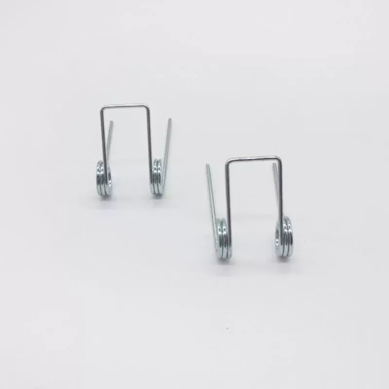
An external parallel double torsion layout places two coil bodies beside one another and connects them through a bridge or specified leg arrangement. The complete layout must show how each body is supported and how movement is transferred. Specify the working angle and torque, including whether the requirement refers to the complete assembly or to each side. Symmetry of appearance does not establish balanced loading.
Use this page for externally separated coil bodies. An internal or concentric arrangement uses a different support envelope. The general double-torsion page is useful when the layout has not yet been selected.
Specify the test fixture, arm contact points and angular reference. Include bridge and leg dimensions in inspection, and define any allowable difference between the two sides when balanced action matters.
Product Specification
Use these product-specific inputs to describe your requirement. Final dimensions, material and performance are confirmed against the drawing and operating conditions.
| Specification item | What to define |
|---|---|
| Paired body geometry | Wire size, both coil diameters, coil widths and centre spacing. |
| Bridge and legs | Connection shape, leg lengths, contact points and free angles. |
| Supports | Shaft sizes, support layout and axial clearances. |
| Torque-angle points | Required torque at defined installed angular positions. |
| Movement and duty | Direction, angle limits, cycling and material requirement. |
Next Design Decisions
Once the spring style is selected, confirm how it works in the assembly, which material suits the environment, how it will be manufactured and which dimensions and performance points should be controlled on the drawing.
Applications
Review best-fit uses, assembly constraints and situations where another spring style may be a better choice.
View application guidance →Materials
Review spring wire and its condition with coil, bridge and leg geometry as well as corrosion and cycle requirements.
Compare spring materials →Manufacturing
Review forming, heat treatment, secondary operations, inspection and the path from first samples to repeat production.
View manufacturing capabilities →Engineering Data
Use the engineering library to review materials, sizing considerations and applicable standards for the custom design.
Open Spring Engineering Guide →Material Direction
The links below are selection guides, not a claim that every grade is suitable for every size or load.
Review the design and measurement requirements for this spring family.
Compare Designs
Use these alternatives when the available space, connection style, travel or force direction changes.
Torsion Springs
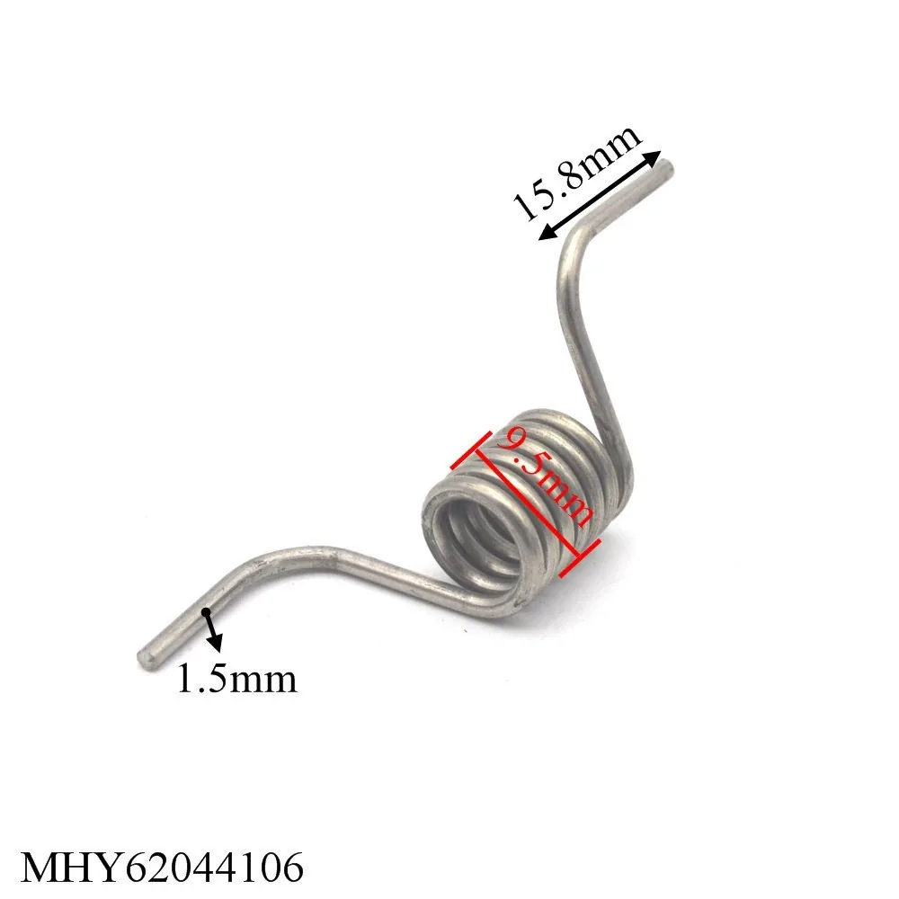
Custom Double Torsion Springs manufactured to your drawing, dimensions, load or torque, material, working environment and production requirements.
Torsion Springs
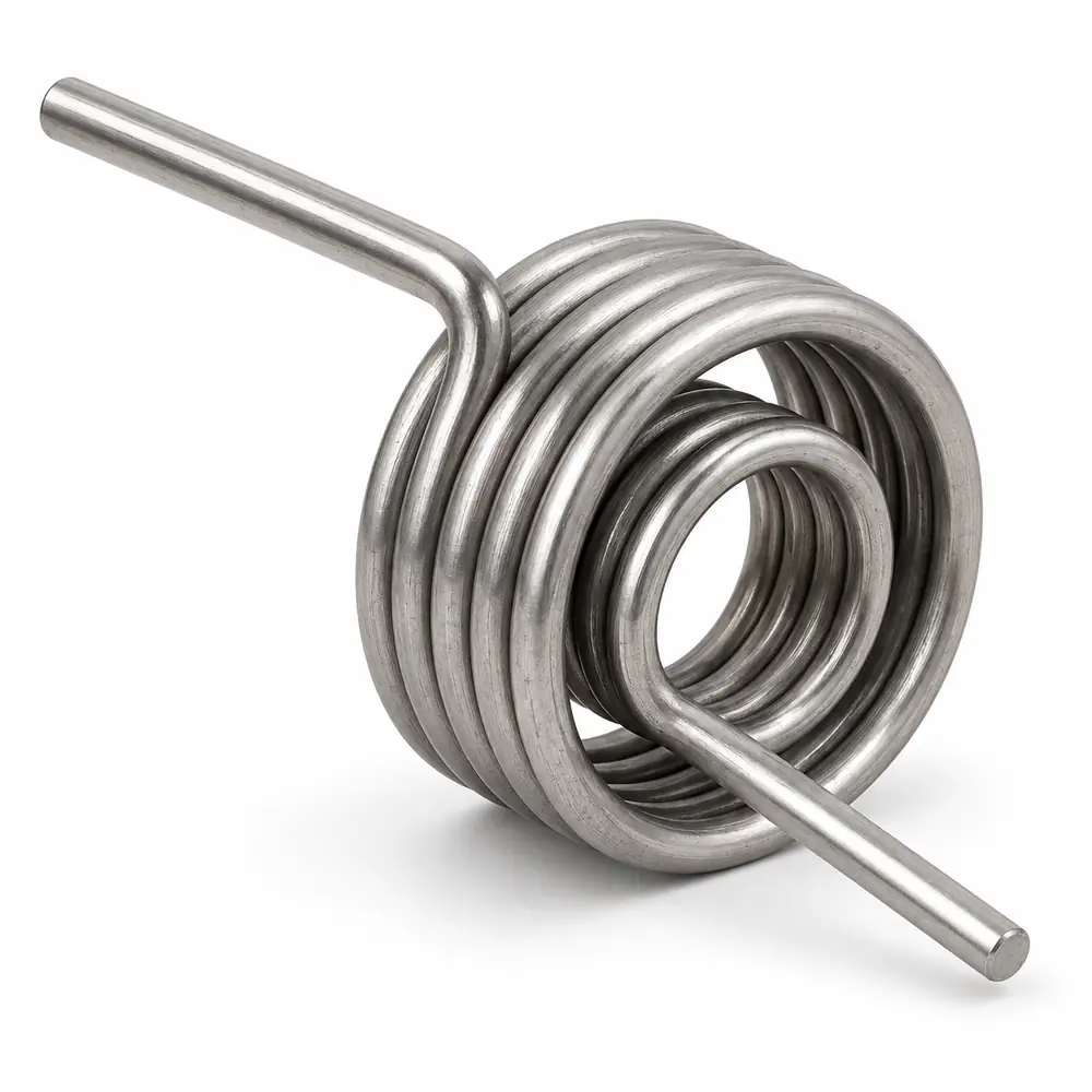
Concentric or internally arranged paired torsion enquiries, defined by the inner and outer coil layout and the actual rotational load path.
Torsion Springs
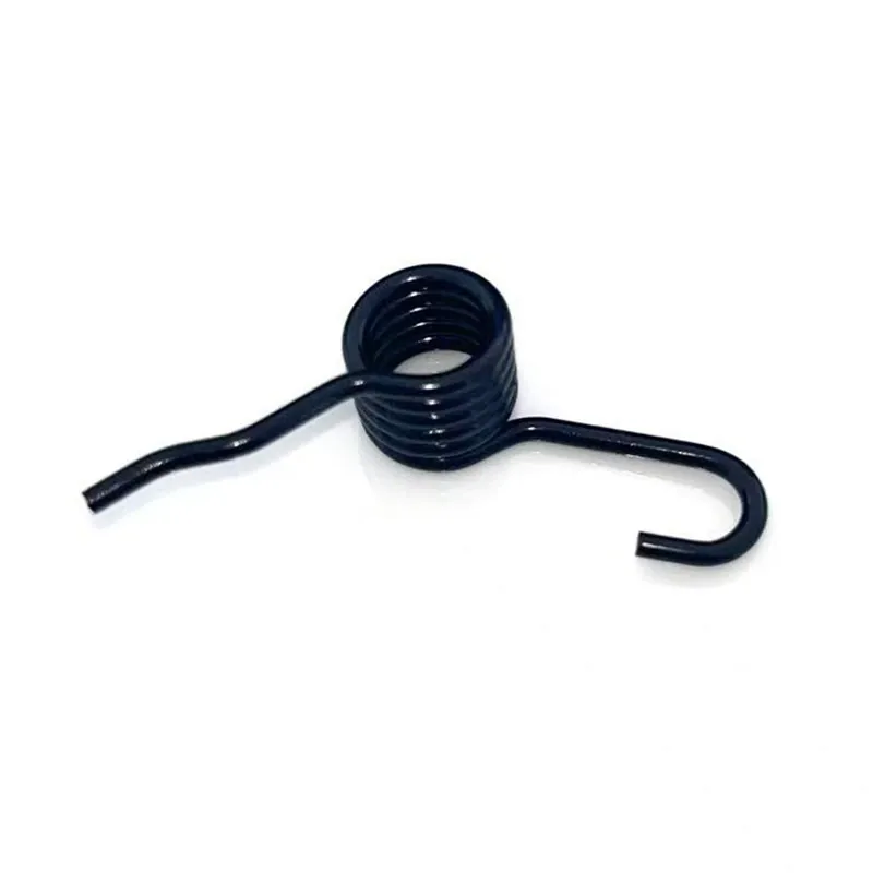
A torsion spring with two working arms used to share rotary load across a wider mechanism or provide balanced return around a common pivot.
Product Questions
Only when the defined assembly loads the two elements together as intended. State the support and movement arrangement, and identify whether the target is total or per-side torque.
Torque must be tied to a reproducible installed position and contact arrangement. Include the free leg positions and working-angle reference on the drawing.
RFQ
A drawing is ideal. If you do not have one yet, provide the dimensions, load or torque, travel, environment and expected quantity that matter in the assembly.
CustomSprings Engineering Catalog
Send your dimensions, quantity and drawing for engineering review.